- 您现在的位置:买卖IC网 > Sheet目录986 > KIT3376MMA7341LC (Freescale Semiconductor)KIT EVAL 3AXIS ANLG ACCELEROMETR
�� �
�
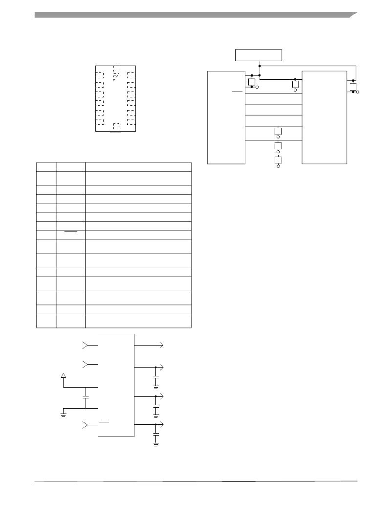
�BASIC� CONNECTIONS�
�Pin� Descriptions�
�Top� View�
�N/C�
�PCB� Layout�
�POWER� SUPPLY�
�N/C�
�X� OUT�
�Y� OUT�
�Self� Test�
�N/C�
�N/C�
�V� DD�
�V� SS�
�Sleep�
�C�
�C�
�V� RH�
�P0�
�V� DD�
�V� SS�
�C�
�Z� OUT�
�V� SS�
�g-Select�
�N/C�
�g-Select�
�Self� Test�
�P1�
�P2�
�V� DD� N/C�
�Sleep�
�Figure� 4.� Pinout� Description�
�Table� 4.� Pin� Descriptions�
�Pin� No.� Pin� Name�
�Description�
�X� OUT�
�Y� OUT�
�Z� OUT�
�C�
�C�
�C�
�A/D� IN�
�A/D� IN�
�A/D� IN�
�1�
�2�
�3�
�4�
�5�
�6�
�7�
�8�
�9�
�10�
�11�
�12�
�13�
�14�
�N/C�
�X� OUT�
�Y� OUT�
�Z� OUT�
�V� SS�
�V� DD�
�Sleep�
�N/C�
�N/C�
�g-Select�
�N/C�
�N/C�
�Self� Test�
�N/C�
�No� internal� connection�
�Leave� unconnected�
�X� direction� output� voltage�
�Y� direction� output� voltage�
�Z� direction� output� voltage�
�Power� Supply� Ground�
�Power� Supply� Input�
�Logic� input� pin� to� enable� product� or� Sleep� Mode�
�No� internal� connection�
�Leave� unconnected�
�No� internal� connection�
�Leave� unconnected�
�Logic� input� pin� to� select� g� level�
�Unused� for� factory� trim�
�Leave� unconnected�
�Unused� for� factory� trim�
�Leave� unconnected�
�Input� pin� to� initiate� Self� Test�
�Unused� for� factory� trim�
�Leave� unconnected�
�Figure� 6.� Recommended� PCB� Layout� for� Interfacing�
�Accelerometer� to� Microcontroller�
�NOTES:�
�1.� Use� 0.1� μF� capacitor� on� V� DD� to� decouple� the� power�
�source.�
�2.� Physical� coupling� distance� of� the� accelerometer� to�
�the� microcontroller� should� be� minimal.�
�3.� Place� a� ground� plane� beneath� the� accelerometer� to�
�reduce� noise,� the� ground� plane� should� be� attached� to�
��4.� Use� a� 3.3� nF� capacitor� on� the� outputs� of� the�
�accelerometer� to� minimize� clock� noise� (from� the�
�switched� capacitor� filter� circuit).�
�5.� PCB� layout� of� power� and� ground� should� not� couple�
�power� supply� noise.�
�6.� Accelerometer� and� microcontroller� should� not� be� a�
�high� current� path.�
�7.� A/D� sampling� rate� and� any� external� power� supply�
�switching� frequency� should� be� selected� such� that�
�Logic�
�Input�
�10�
�g-Select�
�0g-Detect�
�9�
�they� do� not� interfere� with� the� internal� accelerometer�
�sampling� frequency� (11� kHz� for� the� sampling�
�frequency).� This� will� prevent� aliasing� errors.�
�XOUT�
�VDD�
�Logic�
�Input�
�0.1� μF�
�13�
�6�
�Self� Test�
�MMA7341LC�
�VDD�
�YOUT�
�2�
�3�
�3.3� nF�
�8.� 10� M� Ω� or� higher� is� recommended� on� X� OUT� ,� Y� OUT� and�
�Z� OUT� to� prevent� loss� due� to� the� voltage� divider�
�relationship� between� the� internal� 32� k� Ω� resistor� and�
�the� measurement� input� impedance.�
�5�
�VSS�
�3.3� nF�
�Logic�
�Input�
�7�
�Sleep�
�ZOUT�
�4�
�3.3� nF�
�Figure� 5.� Accelerometer� with� Recommended�
�Connection� Diagram�
�MMA7341LC�
�Sensors�
�Freescale� Semiconductor�
�5�
�发布紧急采购,3分钟左右您将得到回复。
相关PDF资料
KIT3376MMA7361LC
KIT EVAL 3AXIS ANLG ACCELEROMETR
KIT3376MMA7361L
KIT EVAL 1.56/6G 3-AXIS ACCELER
KIT3376MMA7368LC
KIT EVAL 3AXIS ANLG ACCELEROMETR
KIT3376MMA7368L
KIT EVAL 3AXIS ANLG ACCELEROMETR
KIT34844AEPEVBE
KIT EVAL BOARD 10CH LED BACKLGHT
KIT3803MMA7660FC
KIT EVALUATION FOR MMA7660FC
KITMMA9550LEVM
KIT EVALUATION FOR MMA955XL
KITMMA955XLEVM
KIT EVALUATION FOR MMA955XL
相关代理商/技术参数
KIT3376MMA7360L
功能描述:加速传感器开发工具 XYZ-AXIS ANALOG ACCELERO RoHS:否 制造商:Murata 工具用于评估:SCA3100-D04 加速:2 g 传感轴:Triple Axis 接口类型:SPI 工作电压:3.3 V
KIT3376MMA7361L
功能描述:加速传感器开发工具 3-AXIS ANALOG OUT 1.5g /6g Dev Kit RoHS:否 制造商:Murata 工具用于评估:SCA3100-D04 加速:2 g 传感轴:Triple Axis 接口类型:SPI 工作电压:3.3 V
KIT3376MMA7361L
制造商:Freescale Semiconductor 功能描述:3-Axis Analog Output Accelerometer Evalu
KIT3376MMA7361LC
功能描述:加速传感器开发工具 3AXIS Angl Accelero Eval Kit RoHS:否 制造商:Murata 工具用于评估:SCA3100-D04 加速:2 g 传感轴:Triple Axis 接口类型:SPI 工作电压:3.3 V
KIT3376MMA7361LC
制造商:Freescale Semiconductor 功能描述:Analog Output Accelerometer Evaluation B
KIT3376MMA7368L
功能描述:加速传感器开发工具 3-AXIS ANALOG OUT 1.5g Dev Kit RoHS:否 制造商:Murata 工具用于评估:SCA3100-D04 加速:2 g 传感轴:Triple Axis 接口类型:SPI 工作电压:3.3 V
KIT3376MMA7368LC
功能描述:加速传感器开发工具 3AXIS Angl Accelero Eval Kit RoHS:否 制造商:Murata 工具用于评估:SCA3100-D04 加速:2 g 传感轴:Triple Axis 接口类型:SPI 工作电压:3.3 V
KIT33794DWBEVM
功能描述:位置传感器开发工具 33794DWB ODS-NITRON EVAL
RoHS:否 制造商:Microchip Technology 工具用于评估: 接口类型: 工作电压: